Home | Gadget | Fuzzy | Lecturer | Power | Transceiver
Gas Flow Meter
R. Pretzenbacher
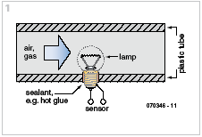
The most surprising thing about this circuit is the sensor that it uses: a 4.5 V miniature torch bulb. The glass envelope is (carefully!) broken and then the pieces of glass removed, leaving just the filament intact. The filament forms the actual sensor element (see
Figure 1).

As you can see from the circuit diagram in
Figure 2, the bulb filament is supplied with 20 mA from a constant current source, with the result that the filament warms up. The current, which can be adjusted using P1, is a compromise between the sensitivity of the unit and its operating life. If the current is too high the filament will reach too high a temperature and sooner or later will burn out. The filament has a positive, although relatively small, temperature coefficient of resistance: the hotter the filament the greater its resistance and so the greater will be the voltage dropped across it at a given constant current.

If air (or another
non-flammable gas) flows through the pipe in which the filament is mounted, the filament will be cooled and the voltage across it will fall. The greater the air flow the cooler the filament and so the lower the voltage. The relationship between flow rate and voltage is reasonably linear. An important use of this measurement technique is in the air intake of car engines, where an ordinary thin heated wire is used as the sensing element in place of the lamp filament. Operational amplifier IC1.A is used to subtract the voltage drop across the coil from a voltage produced by the PICAXE microcontroller (IC3) via its PWM output on pin 5, filtered by the RC-network comprising R9 and C5. The second operational amplifier amplifies the residual signal as needed. The gain can be adjusted using P2.
The PICAXE08M from Revolution Education Ltd is a PIC microcontroller that can be prom grammed in BASIC (see www.picaxe.com). When power is applied the PICAXE automatically goes through the offset calibration procedure, which helps the unit achieve excellent sensitivity. Simultaneously the measured voltage is digitised within the PICAXE. The result of the flow rate measurement is made available both as an analogue voltage (pin 7 of IC1.B) and in digital form on the TTL-level RS-232 output K1. The BASIC program that runs in the PICAXE is available for free download from the Elektor website at http://www.elektor. com, look for file # 070346-11.zip. The NE555 is present only to provide a small negative voltage of around –2 V for the LM358. This lets us use this low-cost operational amplifier in such a way that its output can swing down to 0 V. The NE555 inverter circuit allows the unit as a whole to be powered from a single 5 V supply. Using this circuit the author has obtained a usable output signal from 0 V to 3.5 V when promeasuring very gentle flows from 0 nl/h to only 120 nl/h. He used the circuit to check the operation of an industrial nitrogen (N
2) flow rate meter. It must be admitted that a circuit as simple as the one described here has a few infelicities. The sensitivity of the unit is highly dependent on the filament used and on the current through the filament (although this is compensated for by the calibration that the PICAXE carries out). Also inconvenient is the strong dependency on the temperature of the gas whose flow rate is being measured. To compensate for this the gasflowing through the pipe must be heated to a defined temperature before being passed over the filament. And we cannot emphasise strongly enough:
do not under any circumstances use this circuit with flammable gases!
