
Home | Gadget | Fuzzy | Lecturer | Power | Transceiver
Ballast For Energy Saving Lamps
CFL preheats, ignites and lights on single-chip ballast
1/2008 elektor
For sure, the incandescent bulb that’s been with us for well over a century will be banned soon to the realms of Big Energy Wasters, and from there, to Oblivion. Its function, lighting our desks, streets and rooms is to be taken over, they say, by energy-saving light sources like CFLs (compact fluorescent lamps). As opposed to the good old light bulb, a CFL needs an amount of electronics to start and light properly.
Here we show a suitable circuit.
This compact ballast is intended for driving a 20-watt ‘bare’ CFL tube or bulb, that is, one without a driver circuit built into its socket that makes it ready to screw into an existing lamp socket. Bare CFLs come in many shapes and sizes and usually have four connecting pins. By contrast, (consumer) CFLs sold as direct replacements for the good old incandescent bulb (to be banned shortly, it’s official!) have a ceramic or ABS base and a traditional ‘E’ screw base (where ‘E’ stands for ‘Edison’). These contemporary lamps of which an example is shown in Figure 1, are often referred to as ‘screw base’, ‘internally ballasted’ or ‘self ballasted’ CFLs and can be bought for £ 3.00 to £ 7.00 (€ 4.50 to € 10) depending on the shape and wattage. Our circuit is a separate ballast control for ‘pin-base’ CFLs (Figure 2) more usually found in the industry (already, they’re superseding mercury lighting). Pin-base CFLs are designed to be used with a separate ballast. As with a linear fluorescent system, the lamp and ballast must be compatible. Pin-base CFLs are available in low-power versions to replace incandescent light bulbs and in medium- and high-power versions to take over from linear fluorescent lamps or even high-intensity discharge (HID) lamps. If you want to know more about CFLs and associated ballast circuits, have a look at ref. [1]. If we are to believe what’s written on the box, a 20-watt CFL achieves the same light intensity as a 100 watt incandescent bulb, hence represents an energy saving of at least 75%. However, there are no formal methods to substantiate such claims! Although a CFL, pin-based or self-ballasted, is sure to last much longer than its wolframbased predecessor, the price/lifetime tradeoff is a matter of fierce debates about ‘all things green (and beautiful)’. In this article we will limit ourselves to technical aspects of controlling pin base CFLs.

Figure 1. CFL lamp with an E-style screw base that makes it a direct replacement for incandescent bulbs.
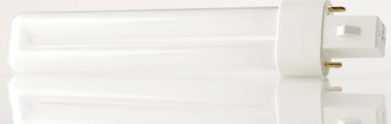
Figure 2. Example of a pin-base CFL. This one has just two pins instead of four but then the capacitor is in the protruding part between the pins.

Figure 3. Circuit diagram of the CFL Ballast. A FAN7710 IC pretty much does it all here. Thanks Fairchild!

Figure 4. Functional block diagram of the FAN7710 (Fairchild).
Figure 5. Clear the kitchen table, but not for dinner! Construction and assembly of the inductor in the circuit.
Making a pin-base CFL light
The circuit shown in Figure 3 uses a dedicated integrated circuit type FAN7710 from our friends at Fairchild. As illustrated in Figure 4, this device combines one high-side 625-V gate driver circuit, two 550-V MOSFETs, a frequency control circuit and a shunt regulator –– plus active ZVS control and an open lamp detection function, all crammed into one ultra-compact 8- way DIP package. Its high functionality and built-in protection features save board space, reduce power dissipation and guarantee enhanced reliability in end systems. Good! The AC line input voltage (here, 230 VAC 50 Hz) is rectified to provide a bus voltage of approximately 320 volts DC. Startup resistor R1 supplies initial (micro-) power to the FAN7710 IC. The IC begins to oscillate and the charge pump circuit consisting of C2, D2 and D7 supplies the current to the V
DD pin, which gets regulated through the internal 15-V shunt regulator. The FAN7710’s oscillator circuitry employs three discrete frequencies: one to pre-heat the CFL gas; one to ignite it and one for the on state — see the inset for the associated (simple) maths. In addition to this, it protects the ballast circuitry from low AC as well as lamp removal conditions. Fuse F1 in the input power supply prevents electric hazards.
Making the inductor
The bare PCB, FAN7710N IC and the 2.5-millihenry inductor used in the circuit come as a set from the Elektor Shop. However we would not discourage anyone from purchasing the inductor parts and making it yourself. Let’s first carefully write down the specifications:
I
nductance: 2.5 mHCore material: Epcos N19 or equivalent
Core size: 20 / 10 / 6
Bobbin: E19
Gap: 1.5 mm
Wire gauge: 0.2 mm (SWG #32)
Number of turns: 280
Now look at Figure 5 for the construction details. First, wind the 280 turns of enamelled copper wire (ECW) on the E19 bobbin. Bare the wire ends for about 5 mm by scratching with a scalpel, then pre-tin. Check continuity of the coil. Put the Ecore halves over the bobbin as shown, then insert and adjust the spacers to get the required air gap of 1.5 mm which is essential to achieve the required inductance. The final step is to wrap electrical isolation tape around the core frame.
The board
Elektor labs have designed a circuit board for the project; the component mounting plan is shown in Figure 6. The copper track layout is available as a free .pdf file from our website at www.elektor.com for those wishing to etch their own circuit board. Reflected and non-reflected artwork is included in the .pdf file for your convenience. Component stuffing is a breeze as only normal size leaded components are used on a spacious board. The wiring to the mains and the lamp, and all connections and connectors in between, should comply with electrical safety guidelines.

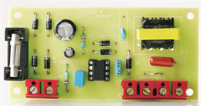
Figure 6. Component mounting plan of the CFL Ballast board. The track layout caters for electrical safety.

Caution
The circuit is connected directly to the mains and presents lethal voltages. Relevant electrical safety precautions must be observed to prevent any component being touched while the circuit is in operation.