Home | Gadget | Fuzzy | Lecturer | Power | Transceiver
Single-transistor timing circuit
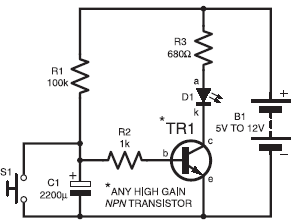
A simple timer can be made using a single transistor, as shown in Fig.1. The transistor, TR1, can be any high gain npn type, a Darlington-pair such as a TIP122 will offer slightly longer timings since its turn-on voltage is 1·4V rather than 0.7V for a “normal” bipolar transistor. When switch S1 is pressed, the voltage at the junction of resistors R1, R2 and capacitor C1 is pulled to 0V. Hence TR1 is turned off, and so too is l.e.d. D1. When the switch is released, current flowing through R1 will cause C1 to charge. This rising voltage will make TR1 turn on once it reaches the threshold of about 0·7V. The delay between releasing the switch and l.e.d. D1 lighting up will depend upon the values of R1 and C1. If the switch is pressed at regular intervals, capacitor C1 will never charge sufficiently to turn on the transistor, and so l.e.d. D1 will never be turned on. When you stop pressing the switch, the circuit will then “time out”, causing D1 to light. This is the principle of classic heart-beat monitoring. Imagine your heart triggering a sensor just like pressing a switch; if your heart stops, the l.e.d., or a warning buzzer, will switch on.

Figure 1. Single-transistor timing circuit
Deficienccies
Transistor TR1 turns on at about 0.7V, and even a large capacitor will quickly charge to this level. Hence the timed period will be quite short. If you try to increase the value of resistor R1, there will come a point when insufficient current is available to switch on the transistor properly. Using an npn Darlington transistor instead of a normal bipolar type will help, because of its higher turn-on threshold of about 1·4V, but the method just described is presented to illustrate the principle, rather than provide a useful circuit. We could improve the circuit by adding more transistors, but there are other much better methods waiting in the wings.
